The deaerator waste heat recovery device, also known as the exhaust steam energy collector, is directly discharged into the atmosphere in all power plants and power stations, causing heat loss and affecting economic benefits, as well as air pollution and environmental issues related to exhaust steam noise.
Introduction to deaerator exhaust steam collector:
The deaerator waste heat recovery device is mostly directly discharged into the atmosphere in various power plants and power stations, causing heat loss, affecting economic benefits, air pollution, exhaust noise and other environmental problems. At the same time, it also occurs in the northern region of China. In winter, when the temperature is low, it produces phenomena such as hanging ice edges at the deaerator exhaust port and large-scale icing in the machine room, Due to the condensation of saturated steam and cold air into water, ice has formed, leading to incidents of falling ice edges and damaging the pressure of the computer room. In order to address these issues, improve economic efficiency, save energy, and eliminate environmental problems, our company has collaborated with research departments to develop a deaerator exhaust steam recovery and utilization device, which has been used in dozens of household appliance factories, power stations, and chemical units. The results are very good, -Received user feedback (this device is suitable for waste heat recovery of heat exchange equipment such as continuous discharge flash tanks and periodic discharge flash tanks, also known as exhaust steam recovery device). With the continuous progress of energy-saving technology and the tilt of macroeconomic regulation policies, 銀行卡energy conservation and emission reduction銀行卡 has changed from passive consumption in the past to active consumption today. It not only caters to the trend, but also brings considerable economic benefits to the implementers. People's concepts - the definitions of 銀行卡waste銀行卡 and 銀行卡waste heat銀行卡 are also undergoing earth shaking changes, and there are many examples of turning waste into treasure. The existing process system generates wastewater (steam) that is directly discharged into the sewage expander. Due to the high temperature of the wastewater, it not only wastes a large amount of available heat energy and purified water, but also has a very adverse impact on the nearby environment due to the emission of a large amount of secondary steam. In order to save energy and reduce emissions, improve economic benefits, and improve the working environment, install high. The steam drum energy harvesting system can save energy by recovering hot water and heating deaerator and other equipment for water intake.
Deaerator waste heat recovery device - standard:
1. The deaerator exhaust steam recovery device shall be designed, manufactured, and accepted in accordance with GB151-1999 Shell and Tube Heat Exchangers and Technical Specifications for Construction and Acceptance of Electric Power Construction.
2. - Safety Technical Supervision Regulations for Pressure Vessels
3. Adopting the GB150-1998 Steel Pressure Vessels standard.
Deaerator waste heat recovery energy collector - benefit analysis:
1. After the installation of the residual steam recovery device in the field of environmental protection, the environmental problems caused by the exhaust of the deaerator, such as exhaust pollution and noise, have been solved.
2. Recovery of exhaust heat and exhaust drainage at a rate of 100T/H
Taking low-pressure deaerator as an example for analysis: output of 100T/H, working pressure of 0.025MPa, working temperature of 104 ℃, saturated steam enthalpy value i=2684kJ/Kg, calculated based on 3Kg per ton of water (Kg/h), then 300Kg of saturated steam is discharged per hour. Approximately 300 hydrophobic materials will be recovered annually (calculated at 7200 hours) × 7200=216000Kg=2160T per ton of drainage (- saline water) calculated at 6 yuan, equivalent to 12960 yuan, while the annual heat emission of a 100T/H low-pressure deaerator is (calculated at 7200 hours per year) 300 yuan × seven thousand and two hundred × 2684=5797440000KJ standard coal has a calorific value of 29271KJ/Kg 5797440000 ÷ 29271=198090.9Kg=198.061T. Therefore, the annual coal savings after the 100T/H low-pressure deaerator is put into the exhaust steam recovery device are 198.00T. Based on the market coal -700 yuan/T, it is equivalent to 138600.00 yuan. The total is 138600+12960=151560.00 yuan. Based on the above single example analysis, one 100t/h low-pressure deaerator, after being put into operation as a deaerator exhaust heat recovery device, plays a significant role in energy conservation, consumption reduction, economic benefits improvement (annual savings of about 150000 yuan), environmental protection, and other aspects. It is a production with both energy conservation and environmental protection.
Installation method of deaerator waste heat recovery device:
1. Just fix the equipment on the platform and connect each interface to the corresponding pipeline. The construction period is about 2-3 days (we will guide the installation)
2. - Pass the remaining gas from the boiler into the cooler, then slowly adjust the flow rate of the makeup water, paying attention to the condition of the upper exhaust and the water temperature of the drainage tank during the adjustment. The cooling water enters the tower body from the inlet and reaches the upper cooling plate. When the water level exceeds the buffer plate, it flows through the cooling holes to the cooling plate, and then flows from the cooling plate to the lower cooling plate.
3. An exhaust valve is installed on the exhaust pipe to adjust the amount of steam and exhaust. When its opening is small, the exhaust volume decreases and the exhaust is not smooth. The gas partial pressure inside the deaerator increases, and the oxygen content in the feedwater does not meet the required standards. As the valve opening increases, the exhaust steam increases, the amount of gas carried increases, and the oxygen content in the feedwater rapidly decreases, but the working fluid and heat loss increase.
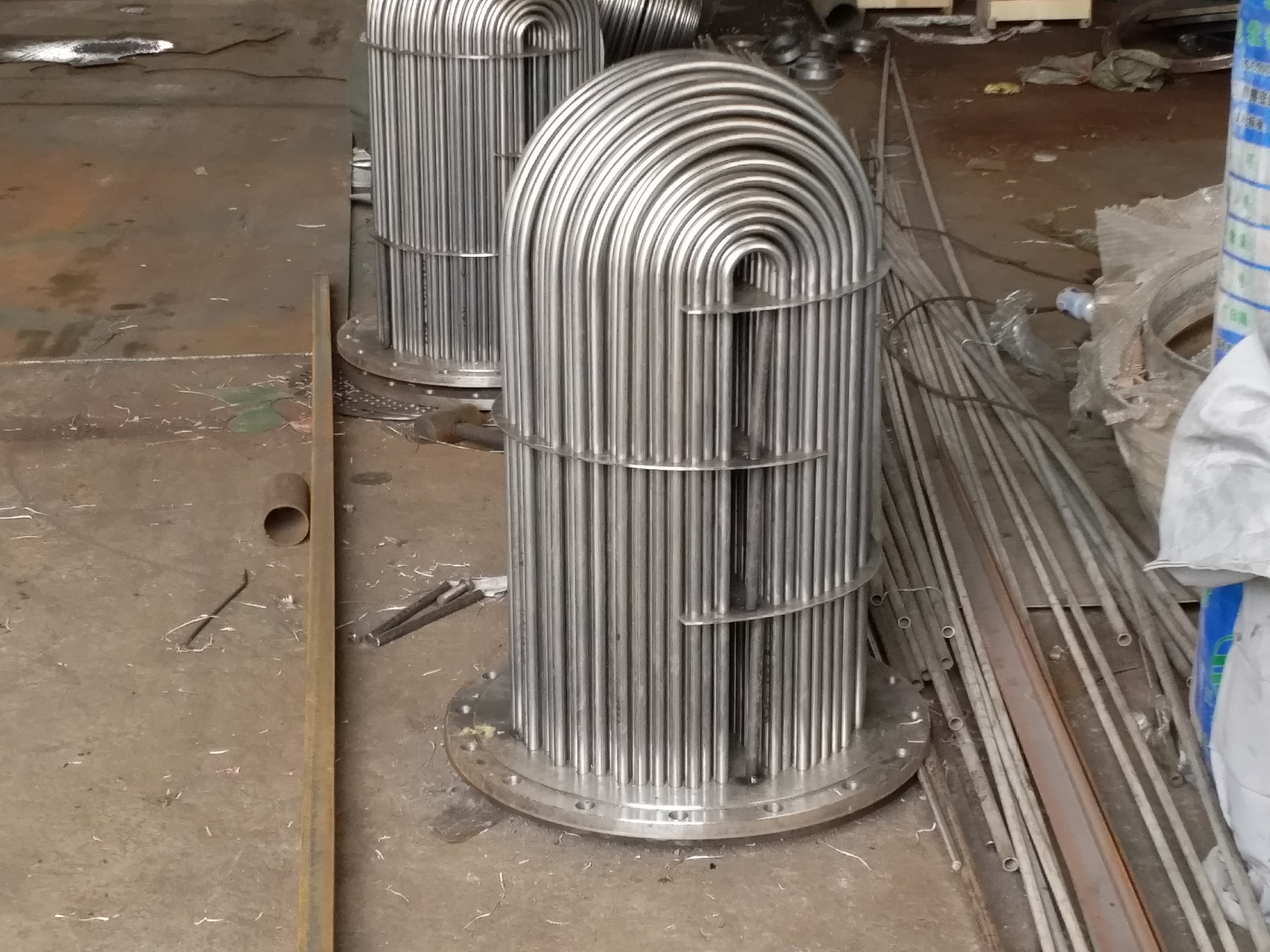
4. The stainless steel plate mesh filler inside the tank is non deformed and non corrosive, and can be used for a long time. It needs to be repaired or replaced. Installing a defoamer at the tank exhaust port can reduce the steam content of the final exhaust.
5. Due to the high oxygen content in the exhaust of the deaerator, in order to prevent it from being dissolved again in the makeup water, it is necessary to reasonably control the proportion of steam and water entering the residual steam recovery tank, so that the tank always maintains appropriate pressure and temperature to facilitate the discharge of oxygen.
Instructions for ordering deaerator exhaust steam recovery:
1. Inform the deaerator output?
2. Exhaust temperature?
3. Exhaust pressure?
4. What is the diameter of the oxygen outlet connecting pipe?
Is it a vertical deaerator waste heat recovery device or a horizontal deaerator energy harvester?
6. Provide the on-site installation location of the deaerator waste heat recovery device?
Deaerator waste heat recovery energy collector -:
1. The exhaust steam recovery structure of the deaerator is simple and requires maintenance for long-term use.
2. Heat and mass transfer results of deaerator exhaust steam collector, energy-saving results.
3. The operation of the deaerator waste heat recovery device is safe and reliable, with no adverse effects occurring.
4. The deaerator and energy harvester eliminate air pollution and noise pollution caused by exhaust, thereby improving the environment.
5. The waste heat recovery of the deaerator increases the inlet temperature of the desalinated water in the deaerator, reduces the content of dissolved oxygen, and plays a role in energy conservation and consumption reduction.
Installation precautions for deaerator waste heat recovery device:
The deaerator exhaust energy collector can be installed on a working platform or on a horizontal ground. During installation, the connections of each pipeline must be tight and tight. And add 60mm glass wool insulation on the outer surface of the equipment.
Deaerator waste heat recovery device - Combined:
Waste heat recovery belongs to secondary energy, which is the product of secondary energy or combustible material conversion, or the heat generated by fuel combustion process after completing a certain process. According to temperature level, industrial waste heat is generally divided into three types: high-temperature waste heat above 600 ℃, high-temperature waste heat between 300-600 ℃, and low-temperature waste heat below 300 ℃; According to the origin, industrial waste heat can be further divided into: flue gas waste heat, cooling medium waste heat, waste steam and wastewater waste heat, chemical reaction heat, high-temperature production and slag waste heat, as well as combustible waste gas and waste heat. Specifically, the residual heat of flue gas is large, with a wide temperature distribution range, accounting for more than 50% of the total industrial waste heat resources. It is distributed in industries such as metallurgy, chemical engineering, building materials, machinery, and power, as well as the exhaust and smoke exhaust of various smelting furnaces, heating furnaces, internal combustion engines, and boilers. In addition, the residual heat of flue gas in some industrial kilns can even reach 30% to 60% of the fuel consumption of the kilns themselves. It has great energy-saving potential and is the main object of waste heat utilization. Cooling medium waste heat refers to the waste heat carried away by cooling media such as air, water, and oil in industrial production to protect high-temperature production equipment or meet process cooling requirements. It belongs to low-temperature waste heat and accounts for 20% of the total industrial waste heat resources. Wastewater, waste steam, and waste heat are low-level steam or condensate waste heat, accounting for approximately 10% to 16% of the total waste heat resources; Chemical reaction waste heat accounts for less than 10% of the total waste heat resources, mainly present in the chemical industry; High temperature production and slag waste heat mainly refer to the heat generated by billets, coke, slag, etc., as well as the heat generated by oil and gas in the petrochemical industry; Combustible waste gas and waste heat refer to the exhaust, liquid, and slag generated during the production process, which contain combustible components such as blast furnace gas and converter gas in the metallurgical industry. Although waste heat resources come from a wide range of temperatures and exist in various forms, from the perspective of waste heat utilization, waste heat resources generally have the following common characteristics: due to the existence of cycles, interruptions, or production fluctuations in the production process, the residual heat is unstable; Waste heat medium - poor quality, such as smoke - high dust content or containing corrosive substances; The waste heat utilization device is limited by inherent conditions such as site and original production. Therefore, the industrial waste heat resource utilization system or equipment operating environment is relatively poor, requiring a wide and stable operating range, adaptability to changing production process requirements, high reliability of equipment components, and high initial investment costs. From an economic perspective, it is necessary to combine process production for the overall design and layout of the system, and combine energy utilization to improve the efficiency of the waste heat utilization system and equipment.
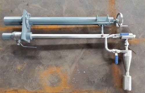
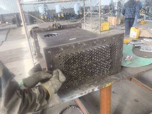
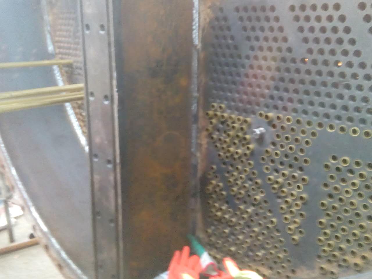
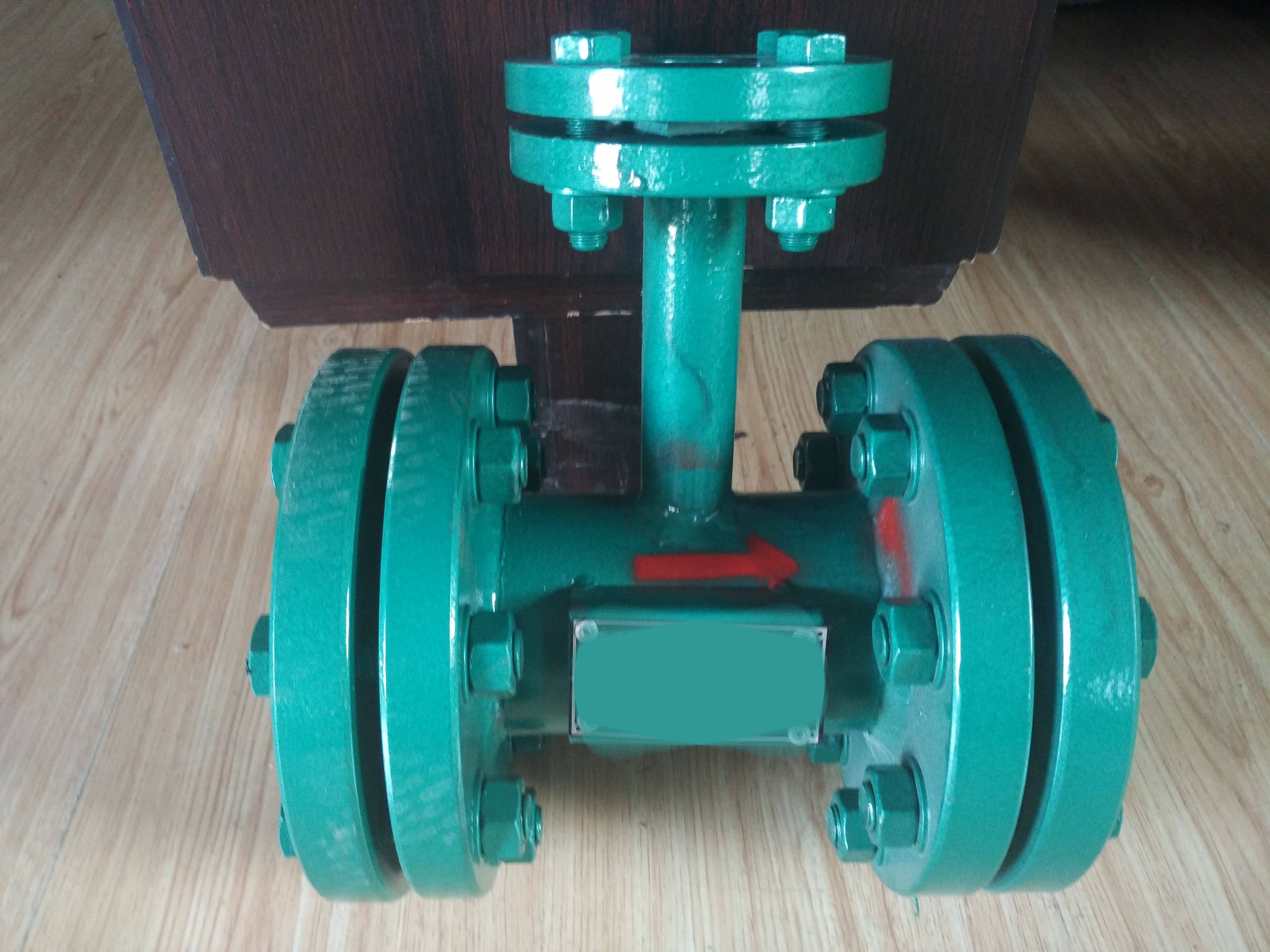
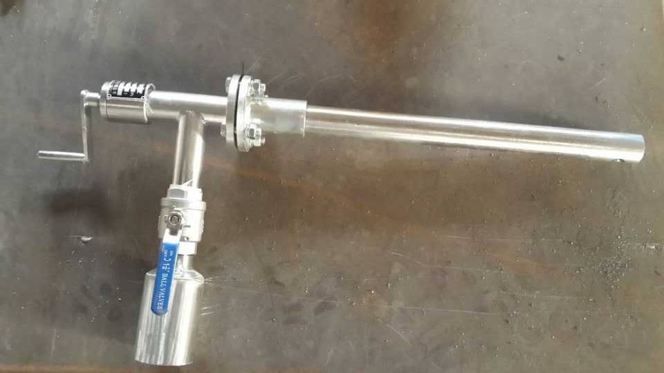
Working principle of deaerator exhaust steam recovery device:
The upper part of the cylinder body of the deaerator energy harvester is equipped with a spray cooling pipe chamber, which is composed of a high-pressure rotary jet injector and a cooling pipe, and its side is connected to a cooling water inlet pipe. Below the spray cooling pipe chamber is the atomization space, and below the atomization space is the heat and mass transfer component. Below the heat and mass transfer component is the steam distributor, which is connected to the exhaust pipe on the side.
This type of exhaust energy harvester is different from the ordinary deaerator residual steam recovery device. It condenses the three heat and mass transfer methods of atomization, water spraying tray, and liquid film into a body, so it has a high efficiency. It not only has a great heat absorption function, but also has strong analytical ability for non condensable gases. The ordinary water spraying and falling film are replaced by strong atomization and falling film, which increases the degree of the liquid film and makes the liquid film strongly entrain a large amount of steam, increasing the heat and mass transfer function.
Introduce the exhaust (steam) of the deaerator into the residual steam recovery tank from the inlet, and combine it with the supplementary water or condensate water introduced from the inlet for mass transfer. Under the action of the internal mass transfer medium, water and steam are fully in contact, and the 銀行卡inlet銀行卡 absorbs the water vapor contained in the 銀行卡inlet銀行卡 and discharges it into the drainage tank from the bottom outlet of the tank. Non condensable gas is discharged into the atmosphere from the tank outlet. The residual steam of the deaerator passes through the cooler, and then the flow of make-up water is adjusted to regulate the water temperature of the drain tank. The cooling water enters the tower body from the inlet and reaches the upper cooling plate. When the water level exceeds the buffer plate, it flows through the cooling holes to the upper cooling plate and then from the cooling plate to the lower cooling plate. During this process, the cooling steam is heated again, and then flows into the drainage tank from the outlet for recycling.
Process flow of deaerator and energy collector:
The cooling water is introduced from the inlet pipe of the deaerator steam collector through the desalination water main pipe, and the deaerator steam is discharged from the deaerator exhaust valve and connected to the energy collector. After sufficient mass and heat transfer inside the equipment, non condensable gas is discharged from the upper exhaust gas outlet. The condensed water flows downward along with the sprayed atomized liquid film, flows out from the outlet, and enters the drainage tank.
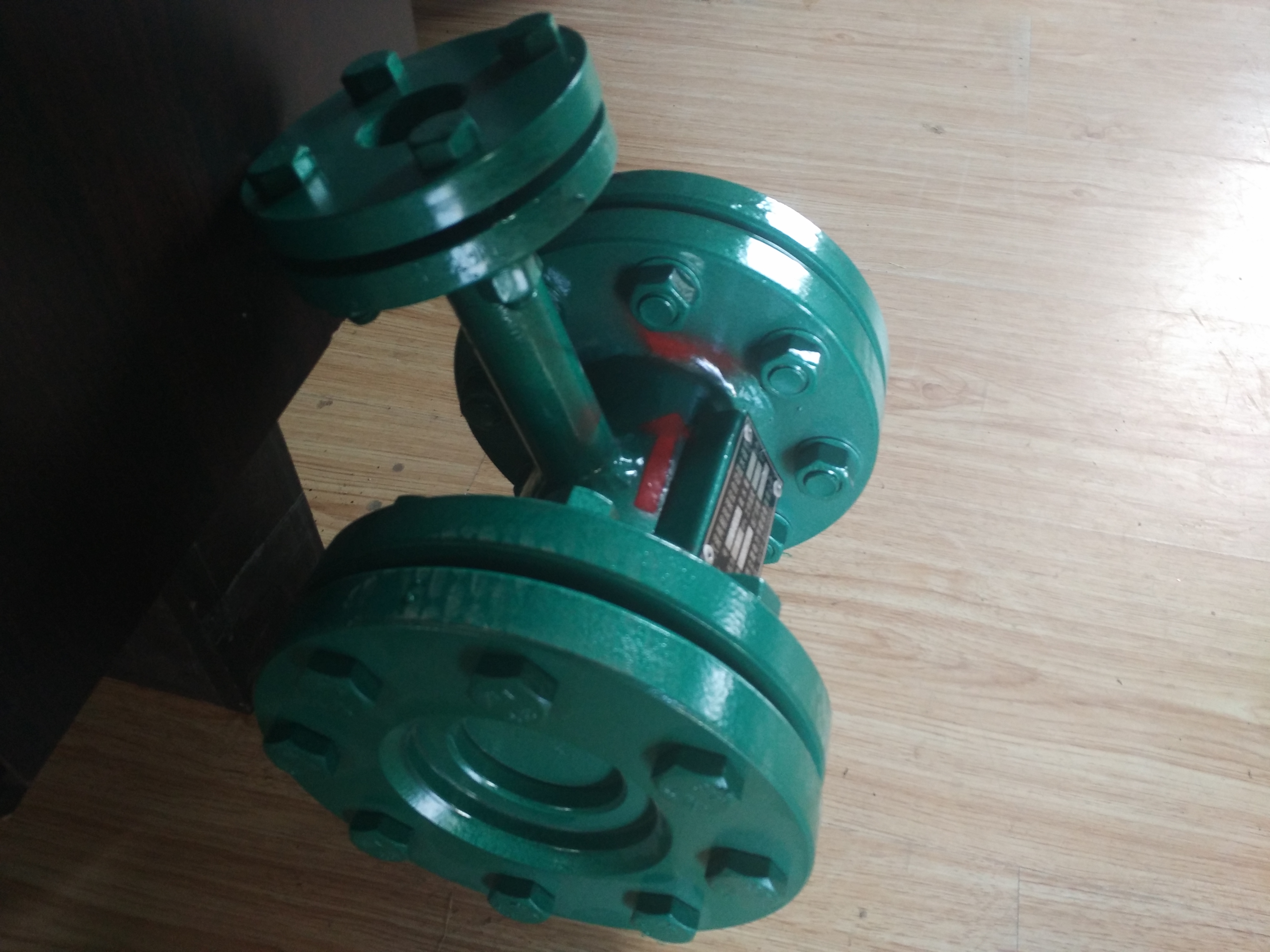
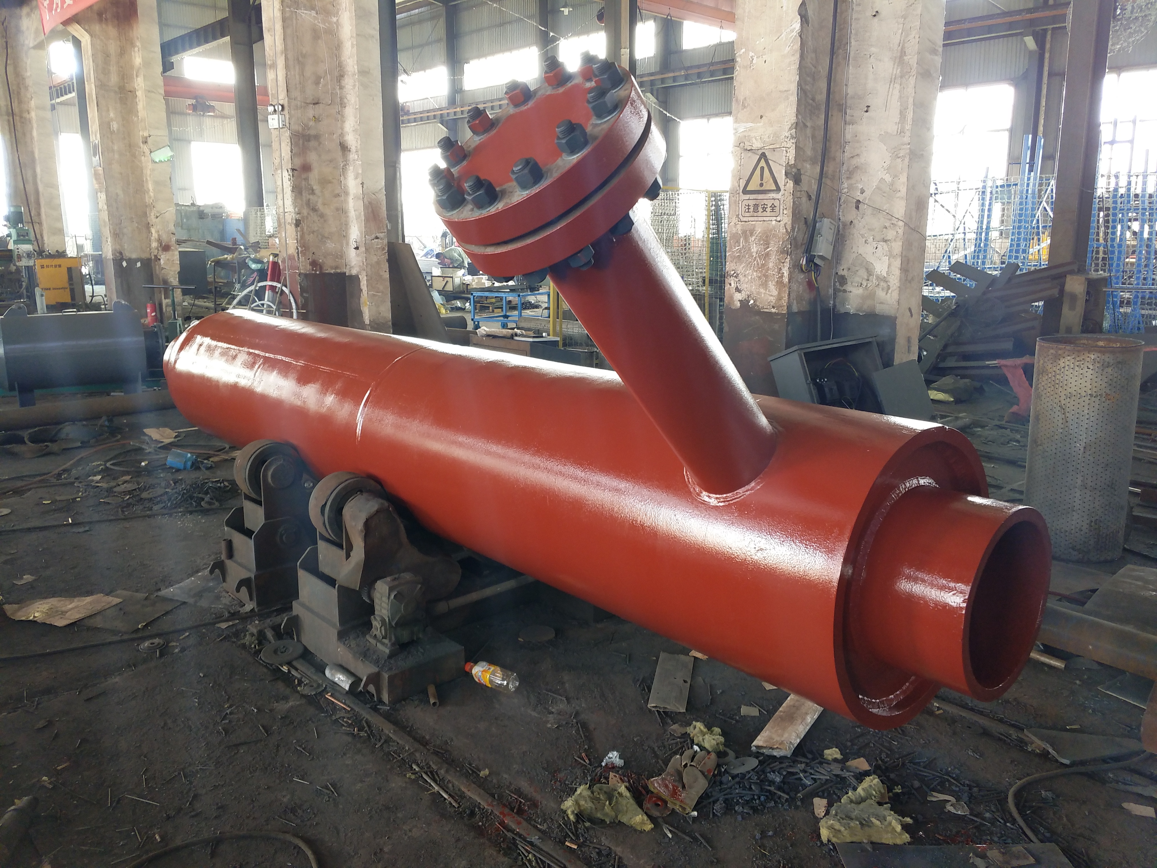
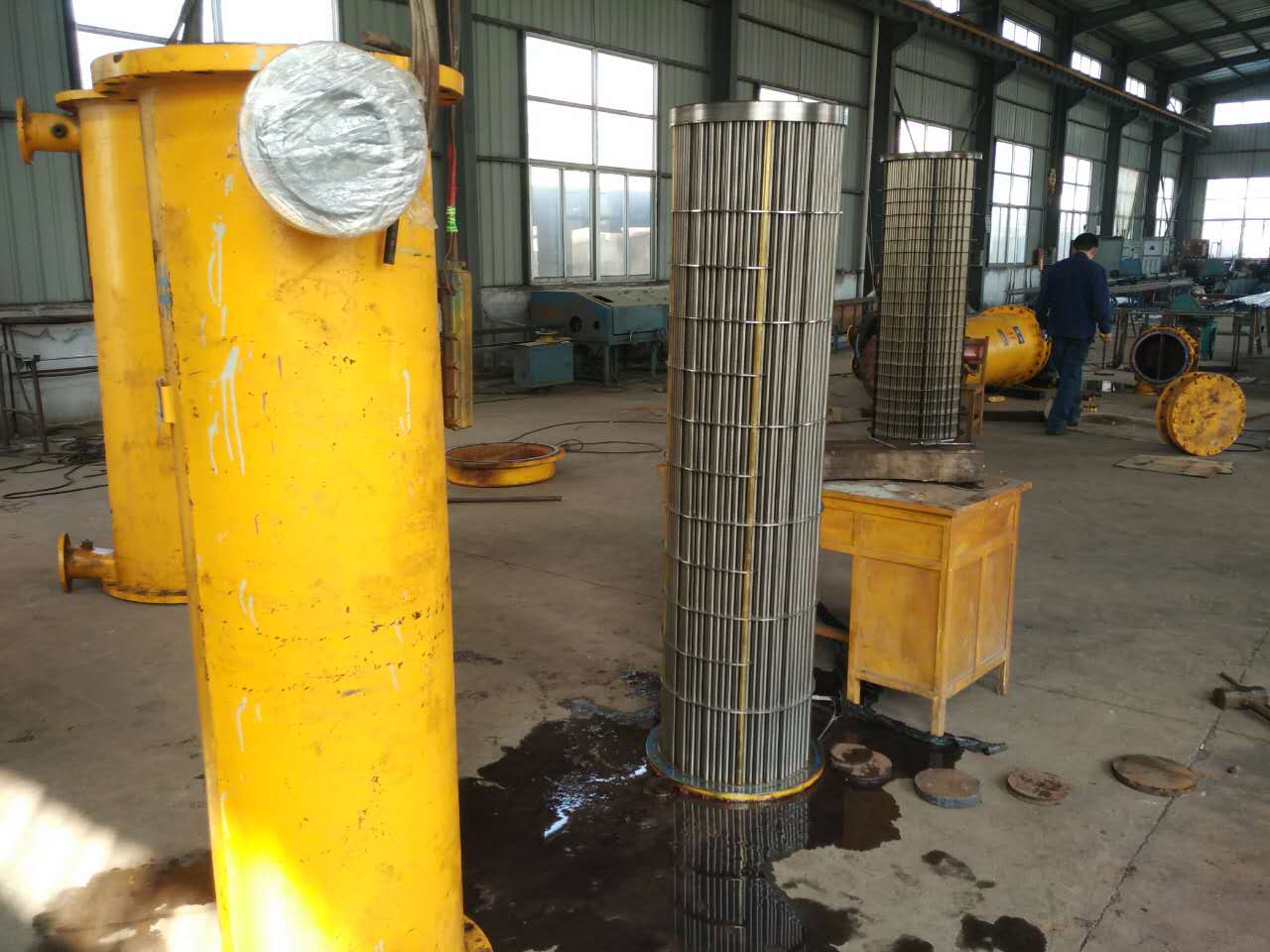
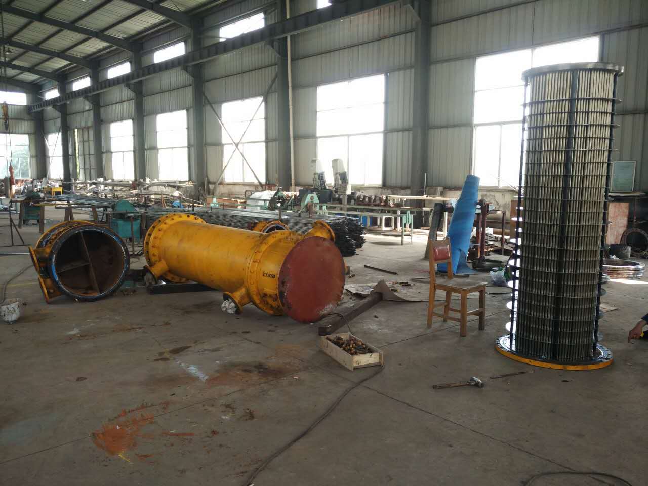
Application of deaerator exhaust steam recovery energy-saving device:
The deaerator waste heat recovery device is a device that cools and recovers the high-temperature residual gas discharged from various boiler deaerator and thermal equipment, while heating the cooling water to fully recycle and reuse the exhaust steam waste heat. This product belongs to the type of energy-saving and consumption reducing equipment, and is an energy-saving and beneficial type of energy-saving equipment. And it is beneficial for controlling exhaust noise.
Deaerator waste heat recovery device energy collector model specifications technical parameters: